DryLin® HTS - Design and assessment
Horizontal
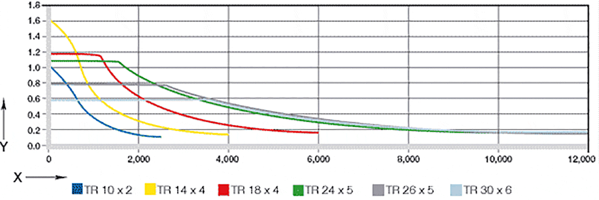
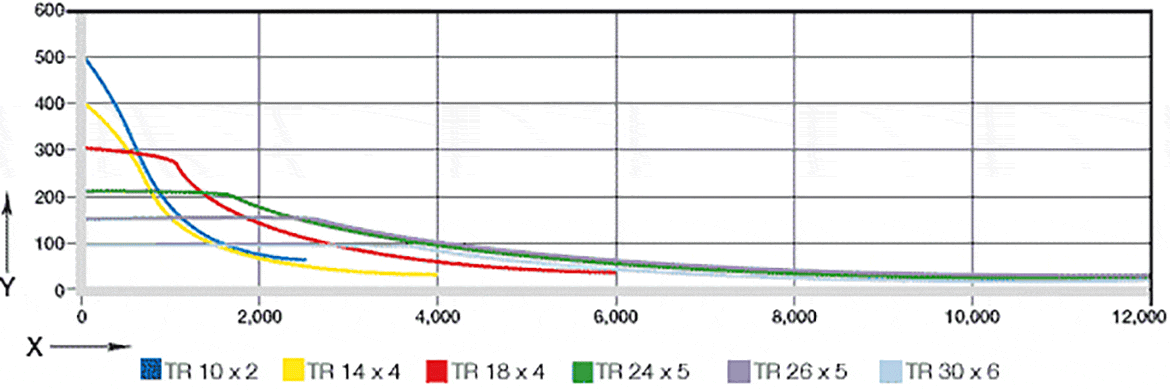
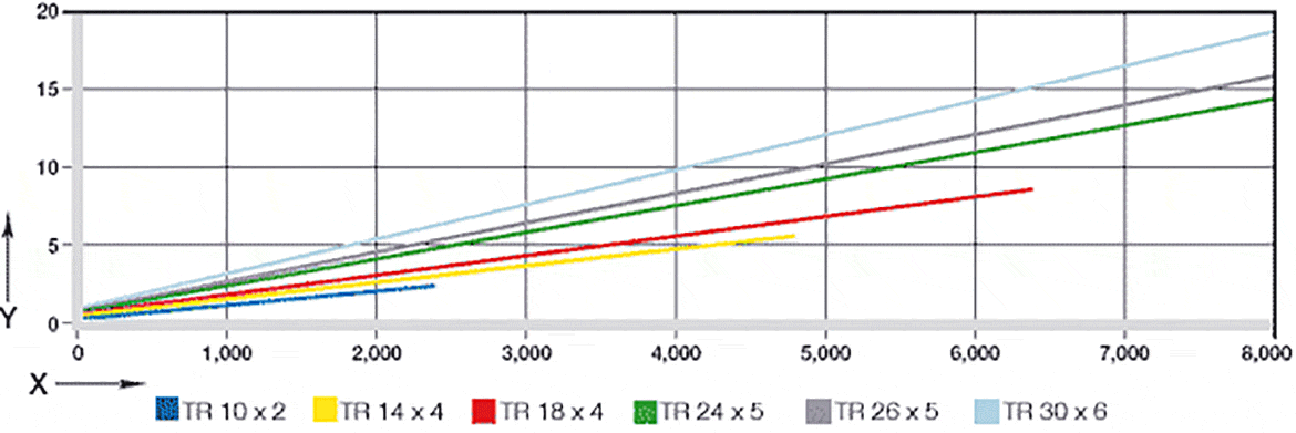
DryLin® spindle linear units are designed for positioning adjustments of all kinds. The linear adjustment is implemented by trapezoidal leadscrews of various sizes or by steep-threaded spindles, which can be operated both manually and by motor. The maximum travel speed amounts up to 1 m/min according to thread and load.The suitability of the spindle-linear units for your application can be checked by means of the diagrams given below.
Following trapezoidal leadscrew sizes are used in the spindle-lift table of the HTS series:
TR 10x2: HTS-12, HTSC-12, HTSP-12, SLW-1040
TR 14x4: SLW-1660
TR 18x4: HTS-20, HTSC-20, SLW-2080
TR 24x5: HTS-30, HTSC-30
TR 26x5: SHTC-40
TR 30x6: SHTC-50
Please note that the loads specified in the diagrams refer to axial loads. For horizontal applications with symmetric load, the following rule of thumb can be used for the conversion of radial force into an axial force:
Faxial = Fradial x 0.25 (for horizontal mounting option)
Faxial = Fradial x 0.25 (for horizontal mounting option)
Max. feed rate[m/min.]

Max. spindle rotation speed [rpm]

Max. drive torque [Nm]
