Cutting in XXL format
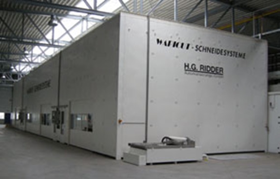
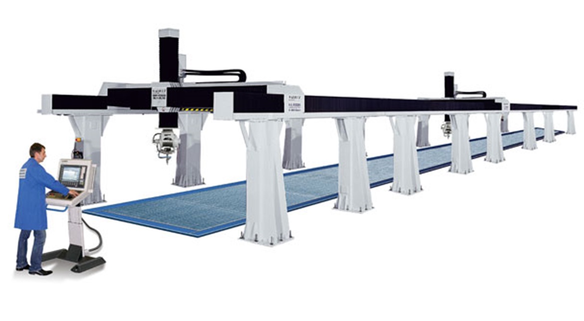
At a travel distance of 105 feet (x-axis) by 16 feet (y-axis), the dual-head 3D water-jet cutting plant, which H.G. Ridder Automatisierungs-GmbH developed and fabricated for the new Anssems Group facility, has noteworthy dimensions. The same also applies to the energy supply systems. These create an important condition for the accurate travel of the two 3D cutting heads on the gantry axes.
Ridder has been known as a specialist for water-jet cutting for thirty years: A water-jet cuts through metals and plastics with the unimaginable pressure of 3,800 bar. The "cold" process has the advantages that the cutting process does not result in harmful emissions and that the cutting surface has an outstanding finish even without post-processing. The cutting process also avoids warping.
From 2D to 3D
Ridder originally developed plants with cutting tables for 2D processing. For 13 years now, the machinery builder has also been building 3D raised gantry plants under the Waricut series. Ridder has now commissioned the to-date largest plant of this kind.
The five axis plant features a cutting volume of 32,050 x 5,050 x 1,900 mm (x/y/z axis). Two gantries, each with one 3D cutting head, travel along the 105 feet long gantry axes. The plant is sectioned into four cabins, so that the two cutting heads can each work on one component while the other two cabins are changed over. This ensures that the plant is continuously in operation. The fact that each cutting head can travel to all four cabins ensures maximum flexibility and availability. All plant components are designed to be corrosion-free.
3D cutting of FGC (fiber-glass composite) superstructures for horse trailers
The customer for this XXL plant is the Dutch Anssems Group, which has developed a well deserved reputation throughout Europe as a manufacturer of passenger vehicle and utility vehicle trailers. Soon, Anssems will also be producing horse trailers in a new 14,000 m² factory that was also built in Bad Bentheim.
This is also where the Ridder made water-jet cutting plant is located. Its job will consist of machining the FGC superstructures that were laminated and molded in a prior processing step, for instance by cutting the door openings. This is done at very high accuracy. Dipl.-Eng. (FH) Dominik Ridder: "Our plants typically work at accuracies of ≤ ± 20 µm per meter - because of the large travels, it is 50 µm for this plant." “
Filled well: The energy supply system
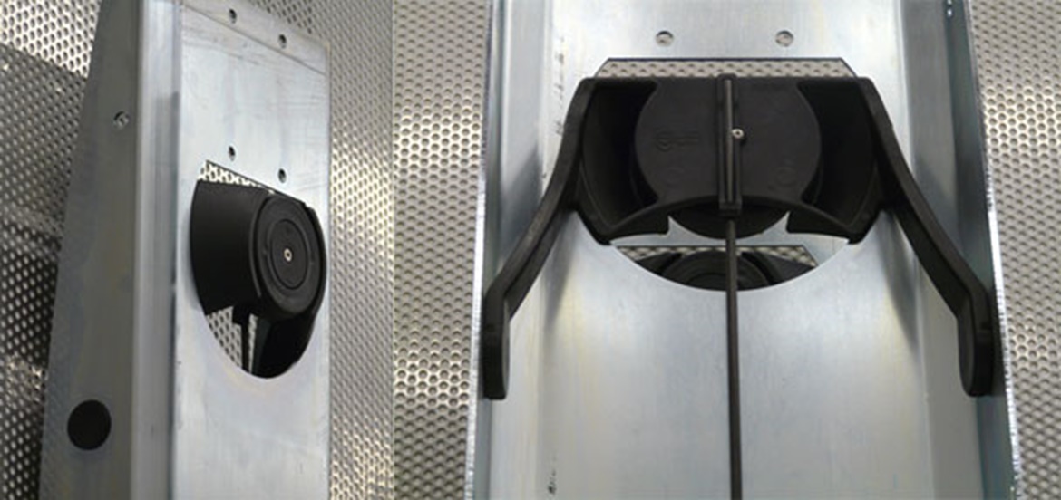
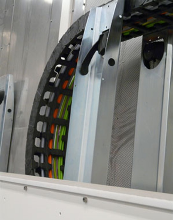
Ridder's engineers needed a solution for supplying the cutting heads with energy, signals, compressed air and - above all - water. The high maximum travel speeds of 20 m/min of the linear axis needed to be taken into account. They decided in favor of a solution that had already proven itself in other Ridder plants: an energy chain from the series E 4.1, made by igus® GmbH, Cologne.
A fair amount of engineering work needed to be done before the energy supply task could be solved optimally. According to the principle of gliding energy chains, the upper run normally simply comes to rest on the lower run. For this plant, this was not possible for two reasons, as explained by igus® sales consultant, Stephan Adamik: "The heavy filling and long travel distance would result in excessive friction. In addition, the high-pressure hose for the water supply called for a larger bending radius, therefore eliminating the ‘chain on chain’ principle."
e-chain® with guidelok-system
In this case, the igus® construction kit provides a suitable solution that was originally developed for machine tool building. Stephan Adamik: "The principle of a gliding chain must be disregarded whenever chips can collect on the upper surface of the lower run because the chips can damage the two chain sections that glide on each other. We developed the guidelok system for these cases, which provides an independent guide for the upper run." “Rolling travel with ideal guidance
Using simple means and only a few components, the guidelok system provides a very stable guide for the upper run, while also significantly extending the unsupported lengths of energy chains. Because the guidelok system guides the chain by means of rollers, chain travel is accomplished at very low pull/push forces, therefore ensuring energy efficient and quiet operation.
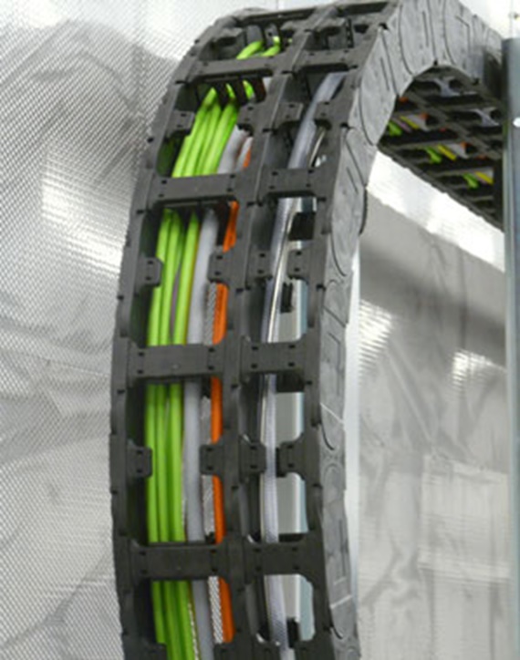
Ridder decided on an e-chain of the igus® series E 4-1 with 100 mm width and 56 mm height. In addition to the ¼ inch high-pressure hose, the chain also guides the chainflex® energy cables for the 3D cutting head and the CANBus communication cables. These were also supplied by igus® and are specially suited for continuous operation. A center crossbar ensures that the high-pressure hose is separated from the electrical cables. In order to keep the two chains as short as possible - given 105 feet of travel - the feed-in is located at the center of the travel distance.
Good experience with FGC machining – and with igus® energy chains
When the plant begins operation, several pallets with trailer superstructures are accurately positioned in each cabin, and a 3D-CAD/CAM program then executes the fully automatic machining of the FGC superstructures.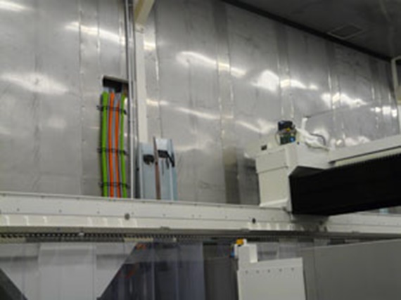
The movable cutting head, which can pivot by ± 95° and rotate by ± 540°, permits cutting even in difficult to access areas. And while the plant executes its programs in two cabins, the other two can already be loaded with new components.
The water-jet exits the cutting head at 3,800 bar and a velocity of 800 m/s, cleanly cutting the very durable material. As exciting as this is from a technical point of view - this is mundane routine for Ridder: The company has already developed and supplied a host of FGC cutting plants, including to the aircraft building industry. Here as well, igus® energy chains were used that have proven themselves under difficult continuous operating conditions.
The water-jet exits the cutting head at 3,800 bar and a velocity of 800 m/s, cleanly cutting the very durable material. As exciting as this is from a technical point of view - this is mundane routine for Ridder: The company has already developed and supplied a host of FGC cutting plants, including to the aircraft building industry. Here as well, igus® energy chains were used that have proven themselves under difficult continuous operating conditions.