Inquiry / Contact
igus® inc.
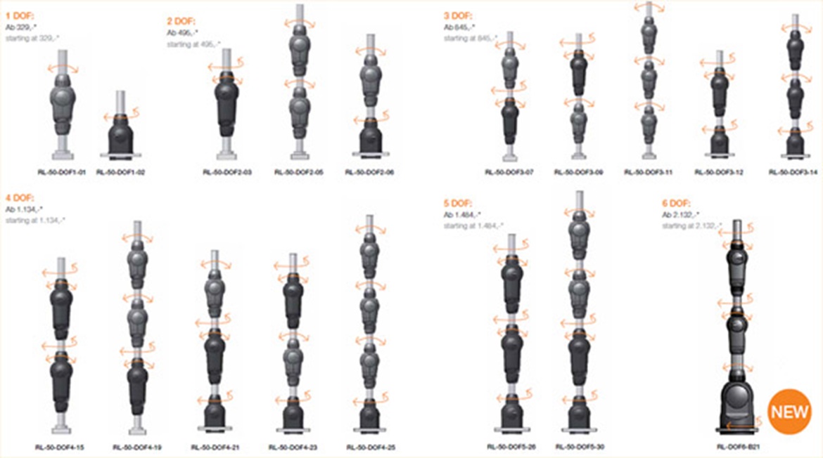
| Ordering number | Number of ropes |
Pivot angle |
Rotation angle |
Weight | Max. Load | ||||
|---|---|---|---|---|---|---|---|---|---|
| On-board drive |
Optional feed- through |
Standard (with stop dog ) |
Option (*without stop dog) |
Standard (with stop dog) |
Option (*without stop dog) |
[gr] | Pivoting [Nm] |
Rotating [Nm] |
|
| 1. Pivoting joint RL-50-PL1 |
2 | 4 | 180° (±90°) | 210° (±105°) |
- | - | 235 | 12 | - |
| 2. swivel joint RL-50-TL1 |
2 | 8 | - | - | 340° (±170°) |
540° (±270°) |
245 | - | 5 |
3. 2 axis |
4 | 4 | 180° (±90°) |
210° (±105°) |
340° (±170°) |
540° (±270°) |
345 | 12 | 5 |
4. 2 axis |
4 | 4 | 180° (+130°/-50°) |
240° (+135°/-105°) |
340° (±170°) |
540° (±270°) |
345 | 12 | 5 |
| 5. 2 axis joint RL-50-003 |
4 | 4 | 180 ° (+180°/0°) |
235° (+180°/-55°) |
340° (±170°) |
540° (±270°) |
400 | 12 | 5 |
| 6. Basic joint RL-90-BL1 |
4 | 8 | 180° (±90°) |
190° (±95°) |
180° (±90°) |
- | 1250 | 20 | 10 |
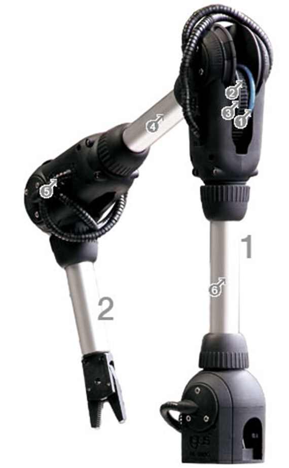
Pneumatic hose (gripper)
24 x Bowden cable system
3Sensor cable - joint 2
44 wires travel freely in the tube
5Individual Bowden cable system for the rotation
68 wires travel freely in the tube
Assembled joint, made from (PA 2200), incl. bearing locations (hard anodized aluminium = standard)
Dyneema® wires
Aluminium rods (standard = 100 mm respectively included, custom lengths on request)
Angle sensors optional (-WS), 3 m sensor cable, assembled and tested. Wire nipple as connecting material, no charge based on consultation.
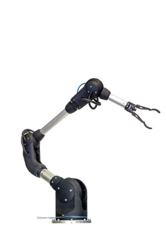
All joints pre-assembled as per item 7)
all wires routed through with special Bowden segments as per item 5)
Aluminium tubes between the joints, tailored to customer specification
Mounting plate at the base of the arm
Sensor cables routed through (option -WS), respectively 3 m of sensor cable assembled and tested. Wire nipple as connecting material, no charge based on consultation.
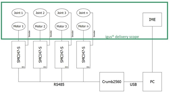
igus® stepper motors, number corresponds to the number of axis in the arm
Planetary gear for each motor
"Drive wheel" to connect the wires to the drive
"Tensioning tool" for convenient re-tensioning of the drive wheels
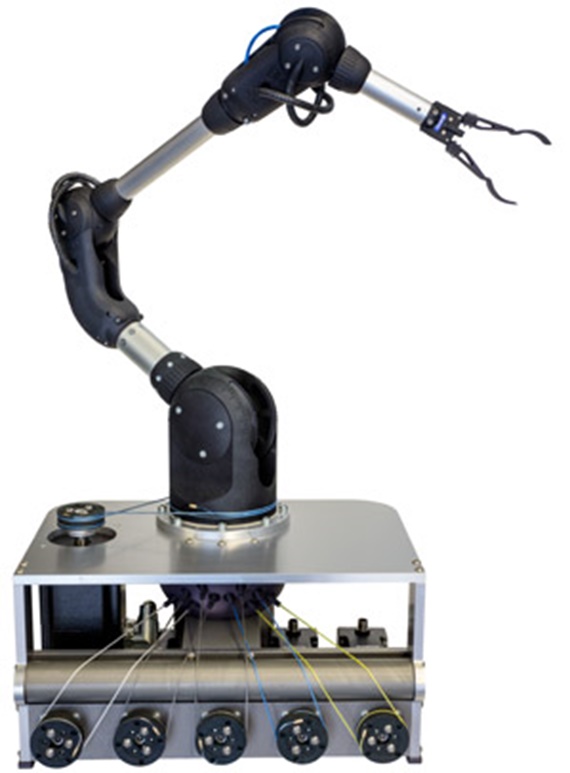
Housings in which the motors are assembled, and on which the arm is built - in various configurations
Grippers (optionally available from igus®, other products can also be adapted)
Control components
Power cables (optionally available from igus®)
4,640 signals / 360° on all rotational motions of joint size RL-50
(29 pole pairs x 160 signals / pole pair) ≈ 0.078°
4,960 signals / 360° on all pivot motions of joint size RL-50
(31 pole pairs x 160 signals / pole pair) ≈ 0.073°
9,920 signals / 360° on all motions of joint size RL-90 ("Base")
(62 pole pairs x 160 signals / pole pair) ≈ 0.036
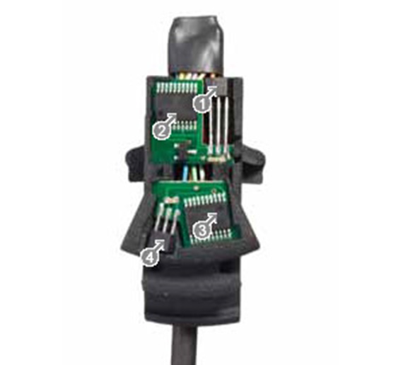
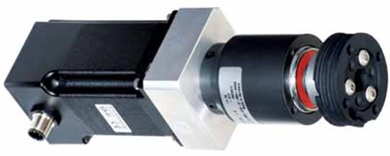
Hall sensor rotating motion
2Encoder rotating motion
3Encoder swivel motion
4Hall sensor rotating motion
Stepper motor
2Planetary gearbox
3Tensionable drive wheel