Change Language :
Caring for Cables
9 Steps for Specifying a Cable Carrier System

Cable carrier pre-harnessed with cables and connectors
What is a cable carrier?
Cable carriers guide and protect cables and hoses on moving machinery. They prevent tangling and damage from debris or contact with the machine itself. Using cable carriers extends the service life of both the cables and the machine. Any application involving moving machinery and constant repetitive motion will benefit from a cable carrier system. Typical applications range from machine tools, woodworking machinery and palletizers, to automated robots, cleanrooms and ship-to-shore cranes.
igus'® line of cable carriers - known as energy chains - are all-plastic, maintenance-free, corrosion-resistant cable carriers. They can replace metal or steel carriers in almost any application. igus offers a variety of Energy Chains such as: micro chains for the smallest applications, E-Z chain for quick assembly, E6 chains for low noise and low vibration, fully enclosed Energy Tubes for applications with flying debris and multi-axis cable carriers for robotic applications.
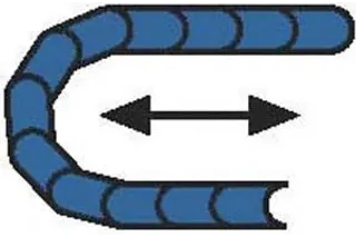
Unsupported short travel
Types of installation
The cable carrier is an integral part of any machine design and should be considered early-on in the design process. It can be implemented in a variety of ways depending on the motion of the machine, but the most common is a horizontal, unsupported, short-travel installation. In this type of application, the upper run of the carrier operates without touching the lower run throughout the entire length of travel. The maximum unsupported length is different for every application, but this type of configuration will have the longest service life (see image A).
If the length of travel is too long for an unsupported installation, it is considered a gliding, long-travel application in which the cable carrier glides on itself (see image B). A guide trough and glide bar must be used to support the carrier. Cable carriers also can be installed vertically or horizontally. Side-mounted, rotary, multiple nested carriers are also quite common.
Here is a step-by-step guide to specifying a cable carrier:
The first question any reputable cable carrier manufacturer will ask is, “What is the largest cable or hose in your system?”
- Gather data: The first step in choosing a cable carrier is to gather all the necessary technical data prior to contacting a cable carrier vendor. This includes length of travel, what cables or hoses will be installed, the size of cables and hoses and how much they weigh, any environmental factors such as debris, heat or chemicals, and speed and acceleration.
- The largest cable or hose: The first question any reputable cable carrier manufacturer will ask is, “What is the largest cable or hose in your system?” This will determine the minimum size of the cable carrier. To this number, add proper clearance - 10% for cables and 20% for hoses - and the resulting dimension is the minimum inner height of the carrier.
- Style, style, style: Next, choose the style of carrier. Always choose a snap-open version whenever possible. This type of carrier allows access to cables with crossbars that snap open at any point along the carrier. If debris or other external conditions are an issue, the tube-style cable carrier replaces the crossbars with lids to fully enclose the carrier and provide complete cable protection. This style is especially useful in applications where woodchips, metal filings and other debris are present. igus® has pioneered various methods of cable access, such as split crossbars, “zippers” or hinged crossbars. With a split crossbar, simply press the conduit into the carrier to install and pull straight up to remove. For zipper-like removal of crossbars, the carrier has interconnected lids that are pulled back like a zipper, removing the top section of the carrier. The hinged crossbars are attached to the side links and are made of non-fiber, reinforced nylon to enable the hinge to flex. These designs minimize assembly and disassembly time. There also are modular cable carriers for heavy-duty, longer-travel applications. They are available with hinged crossbars that are opened on either the inner or outer radius, depending on which is preferable for the application, or with lids to make them into a tube for debris protection. Special cable carriers are available to meet a variety of application requirements. Some are: low-vibration or low-noise carriers, multi-axis carriers for robotic applications, “twister” chains for rotational movements, fully enclosed carriers for protection against metal chips and flying debris, and carriers with integrated wheels for longer travels and less wear.
- The environment:The environmental conditions of an application typically determine which type or style of carrier to use. If debris such as woodchips or metal shards are present, or if the application is in a dirty or contaminated area, an enclosed tube is ideal. An open crossbar carrier is lightweight and facilitates easy inspection and replacement of cables, whereas tube carriers offer removable lids for cable access. Also consider whether the application is underwater or comes in contact with liquids. igus® cable carriers will not corrode and are resistant to chemicals.
Note: Space restrictions Many applications have a space restriction that will affect the design and selection of the cable carrier system. It is imperative that the performance of the system is not compromised to meet these restrictions. There are ways to overcome these restrictions and igus® can work directly with you to choose a cable carrier that meets your design constraints. Keep in mind things such as the camber of the carrier when determining how much height is available for the installation. Camber is the curve of the upper portion of the carrier along its unsupported length. Most cable carriers are manufactured with camber, but special, no camber carriers are usually available upon request. Be advised however, that carriers without camber do not have the same load-bearing capacity as those with camber.
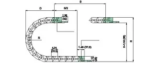
R = the radius of the carrier.
H = the measurement from the top of the curve to the bottom of the curve, or overall curve height.
D = the depth of the curve.
5. Bend Radius: All cable carriers have a predetermined radius stopping point on each link. When a number of links are assembled, these stopping points restrict the carrier from fully pivoting and form a curve loop or minimum bend radius. All cable carriers have multiple bend radii to choose from and all manufacturers suggest a minimum bend radius. If this is unknown, the general rule is 8-10 times the outer diameter of the largest cable or hose. The larger the bend radius, the less stress is placed on the cable and the longer the service life will be. Bend radius is measured from the center of the curve loop to the center of the pivot pin on the side link. Do not confuse this with the dimension of the overall curve height.
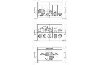
Distribution rules are necessary because cables and hoses must be able to move freely at all times and tensile force must be prevented at the radius of the cable carrier.
6 Cable and hose packages: Since the primary function of a cable carrier system is to ensure cables bend properly, it is imperative to install the conduits correctly. To ensure maximum cycle life for your machine, the easiest solution is to use cables designed for use in a cable carrier. chainflex® continuous-flex cables are designed specifically for use in energy chains.
chainflex® cables follow these seven guidelines:
- Strain-relieving core: The center of a cable should be filled with a genuine core center to protect the cable core structure above and prevent conductors from falling into the center.
- Conductor structure: Medium to fine strand diameter is preferable. igus® uses a combination of single-wire diameter, pitch length and pitch direction to achieve the best performance.
- Core insulation: Insulation materials must be friction-resistant to one another within the cable. Insulation must also protect the stranded wires of the conductor. High-quality PVC or TPE should be used.
- Cable core: Conductors should be bundled into groups and cabled together in a single layer around the core, enabling pulling and compressing forces to cancel out any torsional forces. Special attention should be given to pitch length and pitch direction. Cables constructed in layers are not suitable for long-travel.
- Inner jacket: A gusset-filling extruded inner jacket should be used instead of inexpensive fleece wrap or filler to ensure the cable structure is efficiently guided in the linear direction. This jacket design ensures the jacket maintains the integrity of the cable core.
- Shield design: High-quality braided shields protect cables from electromagnetic interference and an optimized braid angle increases torsional stability. Each chainflex® cable has a shield with an optical coverage of 90%, which yields higher shield effective.
- Outer jacket: Outer jackets must be UV-, abrasion-, and temperature-resistant and resistant to oils and chemicals. It also should not adhere and be flexible while providing support.
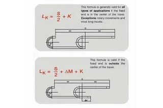
7 Cable carrier length: To determine how long a cable carrier your application will require, first determine the position of the fixed end. The ideal and most cost-effective position is at the center of travel. This will require the minimum amount of carrier to achieve the necessary movement.
- Use the following formula to determine the necessary cable carrier length:
- S = Maximum machine travel distance
K = Curve length
L K = Carrier length
R = Bending Radius
∆M = Deviation from the center point
L K = S/2 + K Use this formula if the fixed end is anything other than the center of travel
L K = S/2 + ∆M + K
8 Acceleration and inertia: It is critical to ensure that the cable carrier is strong enough to support the application. If it isn’t, the results can be devastating. The carrier can literally snap in two. In order to ascertain that the carrier is strong enough, use the following formula to determine the force required for your application.
- First, determine the acceleration force. Acceleration force is the force required to keep the cable carrier moving once it has started.
- Acceleration Force (lb) = Total Weight lb (carrier and fill) x Acceleration ft/sec 2
- Then determine the push force. Push force is the force required to get the cable carrier moving and overcome inertia.
- Push Force (lb) = Total Weight x COF
- Once those numbers are determined, calculate the force of the application by:
- Acceleration Force + Push Force = Force Required
- The force required must be less than the maximum force for the selected carrier. Cable carrier manufacturers typically do not publish the maximum force allowance for their products, but igus® technicians will calculate the force required for your application and select the proper size carrier to meet this requirement.
9 Accessories: A variety of accessories are designed to further facilitate the energy supply system. They can include:
- Interior separators or shelvesensure proper alignment of the cables within the carrier and prevent friction, tangling and corkscrewing. These are available in both vertical and horizontal implementations.
- Mounting brackets are almost always required to attach the carrier system to the machine itself. Plastic or steel brackets made of a single piece are for smaller carriers. Others have aluminum bushings in the bracket to prevent damage when tightening the bolts. These can either pivot for standard applications or lock into place for vertical or side-mounted, gliding applications.
- Guide troughs are available for long-travel applications
- Rollers can be used for even longer-travel applications.
- Extender crossbars enable the use of oversized conduits.
- Strain relief Strain relief is another common accessory designed to keep cables in position at both ends of the carrier. Sometimes strain relief at just the moving end is sufficient, depending on the application, and hydraulic or other fluid hoses should only be strain relieved on the moving end.
- Strain relief can consist of profile rails, clamps, tie wraps and tie wrap plates. Improper, or lack of, strain relief is a common cause of cable and hose failure. The strain relief clamps hold the cable in the neutral axis of the carrier. This prevents the cables from being pulled against the inner radius of the carrier or pushed against the outer radius of the carrier where it can be damaged or incur wear. While it may seem like an insignificant point, strain relief can often make - or break - the success of an application.
Of course, specifying a cable carrier can be a complicated process, but only if you opt to Do-It-Yourself. Instead, consider asking igus® to help you with your application. We have years of experience and can make suggestions based on your application parameters.
Discuss your project with an expert
Whether you're interested in end-to-end, fully assembled solutions or looking to build your own customizable project, let us assist you with a solution based on your specific application and requirements. Contact us via the form below or call us at (800) 521-2747 to discuss your project today!