Change Language :
Gliding - long travels
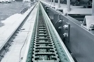
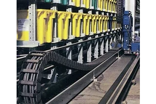
Conveyor belt in quarry. Gliding application with travel distance of 587 ft, travel speed 220 ft/min., fill weight 5.4 lbs/ft
Advantages for long travel applications with igus® energy chains
- Travels over 1,312 ft
- Gliding speeds up to 16.4 ft/s (more in individual cases)
- Service life of 10 years and more with igus® energy chain systems
Further advantages of the design are:
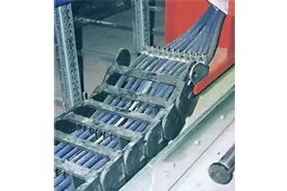
- Many different types of cables and hoses can operate side-by-side in the same system (i.e. electrical, data, fiber optic cables with hydraulic and pneumatic hoses)
- Space-saving installation
- Quiet operation
- High accelerations
- Durable in wind, weather, dirt, and chemicals
- Simple assembly of the modular system on the spot
- Rapid assembly and replacement of cables and hoses
Gliding application:
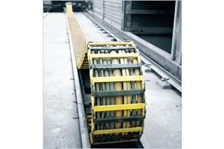
If the upper run of the energy chain cable carrier rests on the lower run, it is a gliding application
- Over 1,300 ft travel
- 16.4 ft/s speed
- Fill weights up to 47 lbs/ft
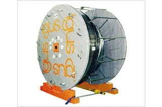
Long travel "off the reel." Up to 328 ft travel pre-assembled and ready to install
Design assistance, free of charge
We recommend that igus® calculate every gliding application for you. We will always offer the most cost-effective solution and take the technical requirements and operational safety into consideration.
To be able to advise you accurately, we require the following specifications:
- Travel [ft]
- Travel speed [ft/min] or [ft/s]
- Acceleration [ft/s²]2]
- Fill weight [lbs/ft]
- Maximum cable/hose outer diameter [inches]
- Type and number of cables and hoses
- Required bending radius [inches]
- Cycle frequency (n/day or n/hour)
- Technical environment
Please call us and within hours you will receive a detailed system proposal
igus® laboratory and practical experience
Our calculations and analyses are based on the results of ongoing practical tests in our Technical Center, as well as the cable carrier experience we've built up over more then three decades. The focal points of our tests include push-pull forces, friction values and wear under widely varying conditions and speeds. We also look at factors such as dirt, weathering, or impacts and bumps. In addition to our cable carriers, we test all our system components, including cables, hoses, strain reliefs, guide troughs and other accessories.
Trends in long travel applications
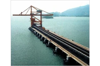
Very long travels with igus Rol E-Chain. - Rolling instead of gliding:
75% less push-/pull forces due to special roller-links. Travels over 2,600 ft are possible. At present, the longest travel length is a Ship-to-Shore crane in Malaysia: 1,448 ft with Rol energy chain 5050R
Long travel "off the reel."
Custom-made energy chain systems complete with cables, connectors, and strain reliefs - are delivered on the reel and rolled off into preassembled guide troughs. This way, time savings of 50% are possible.
Long travels without guide troughs:
Our AUTO-GLIDE system consists of self-guiding energy chains for travels up to 164 ft travel lengths (speed 4.92 ft/s) due to special gliding elements on the crossbars. Usually essential, a guide trough is not required with this type of energy chain.
Long travels with small energy chain:
The Micro flizz® system offers the potential to safely guide power, data and media in a small energy chain with high acceleration in long travels. The components are protected against dirt and weathering and offer a completely maintenance-free operation.
Preferred energy chain - gliding, long travel
Example of a lowered mounting height cable carrier
Gliding application and igus® energy chains
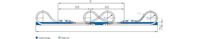
For long travels, the upper run of the energy chain rests on the lower run. The upper run glides partially on the lower run and partially at the same height on a glide bar (see image below). For lateral guidance, a guide trough is necessary. If the stationary mounting bracket and the fixed end of the cables and hoses can be placed in the center, the chain length is calculated as follows: Depending on the technical data and the selected energy chain, the mounting point of the moving end of the energy chain must be lowered on some units.
With our system analysis for long travels, we give exact details for your specific application.
Advantages lowered moving end
- Space saving
- Longer travels possible
- Higher service life due to less wear
Gliding applications =
pivoting mounting brackets

The function of an energy chain system for gliding applications (schematically): the fixed end of the energy chain is located in the center of the distance to be traveled.
Solution with two inversely arranged energy chain systems. The complete travel is arranged thus.
Application in crowded spaces and high loads.
energy chain length:
Lk = S/2 + K
S = Length of travel
R = Bending radius
HRi= Trough inner height
HF= Required clearance height
K2= Further add-on if the mounting bracket location is set lower
K = π * R + "safety" Add-on for bending radius (K is taken from the data tables of the individual igus® Series
D2= Over length for long travels gliding


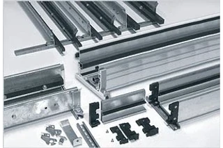
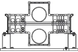
Guide troughs
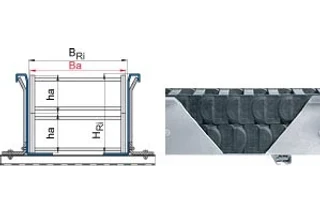
The guide trough is an important element in long travel applications. Unifilar drawings can be found on this page. Usually, the height of the trough must be at least twice that of the energy chain link height. The sides must provide a chamfered opening. The trough inner width is the same as the energy chain outer width, plus 0.2 inches(BRi= Ba + ≈5).Along the side of the trough, where the upper run cannot glide on the lower run, glide bars must be installed. We recommend the use of polymer glide bars from igus®. They are optimally matched to the energy chain material and achieve the lowest values for friction, noise and wear. Guide troughs with and without glide bars can be obtained for almost all igus® energy chains.
Important: when assembling the trough parts, the following points must be given particular attention:
- Properly align all trough parts upon installation
- All screw heads should be flush with the trough
- There should be a smooth leveled transition between the end of the energy chain and the glide bars
- Solid connection with the glide surface. These points must be observed when using assembly-friendly igus® guide troughs.
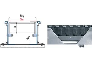
Ba = energy chain outer width
ha = energy chain outer height
HRi = Inner trough height
BRi = Inner trough width
HRi ≥ 2 * ha
BRi ≥ Ba + ≈ 0.2 inches
If the fixed point is in the center of the travel, use half of the guide trough with glide bars and the other half of the guide trough without glide bars.
Guide troughs allow igus® energy chain cable carriers to operate smoothly and with limited friction in long-travel applications. Various guide trough systems are available.
Source: igus® laboratory
| igumid G | igus® polymer bar igulen | Glide sheet steel | Anodized aluminum | Stainless steel |
|---|---|---|---|---|
| Friction value dynamic | 0.19 | 0.45 | 0.54 | 0.48 |
Travel speeds and accelerations
energy chains can achieve speeds up to 16.4 ft/s in continuous operation and are doing just that in existing applications. In special cases, even higher speeds are possible. For example, E4/00 and E4/4 energy chains achieve speeds of 72 ft/s and accelerations of 2,572 ft/s² in crash test units. Only a few thousand cycles per year are required in this situation. Acceleration plays a large role in the calculation. Differentiations must be made between normal operational acceleration and a sudden jolt in acceleration, such as an unexpected stop. Even in these situations, igus® energy chains prove to be very durable.
Service life
We offer service life calculations for your application based on our extensive gliding application experience. As developers of polymer plain bearings, we possess vast material behavior knowledge which we apply to the development of our energy chains as well. Units with over 650 ft travels have been in operation for 8 years with minimal maintenance. Units up to 197 ft travels have been in operation for 12 years with almost no maintenance. Please consult igus® for references and calculations for your project. The maintenance-free aspects of igus® EChainSystems® over long periods and under demanding operating conditions is often the deciding factor in choosing igus®. Our system guarantee (depends on the application) provides additional peace of mind.
Special properties - Long travel applications
energy chains that are nested can be used in gliding applications. This type of installation is most often used when there is a width restriction. Guide troughs with special wall heights are necessary. energy chains running side by side, or in a "multiband" design can also be used in gliding applications. Higher fill weights often require special guide troughs which can be delivered either from stock or on short notice. Higher fill weights are often a reason for this solution. We have also developed standard parts for unconventional solutions involving large hoses in gliding applications. We have developed standard parts for this purpose, which we'd be glad to offer you on request.
Technical environment
Long travel applications using igus® energy chains run in water, in dirt, in the tropics, in explosion-risk areas (energy chains with special design features) and many other conditions. You will find more details in the Technical Environment section of this chapter. Guide troughs can be supplied in corrosion-free materials.
Calculation
Comprehensive testing means we know our products inside out. Important factors in these tests are:
- Push-pull forces under both ambient and extreme temperatures. Humidity and dirt.
- Friction values of the polymers, alone and against various glide surfaces
- Behavior of electrical conduits under push-pull conditions
- Behavior of hydraulic and media hoses under push-pull conditions
- Service life, and noise generation.
Large hose elements
If we can not calculate your application based on these factors, we will perform a practical test for you in our laboratory. Please consult igus®.
Corrosion-free guide troughs are available in the material:
- Normally galvanized
- Stainless steel
- Seawater-resistant aluminum
Technical data - long travels
| Travel max | 1,312 ft (2,625 ft) |
|---|---|
| Travel speed max | 16.4 ft/s |
| Travel acceleration max | dependent on calculation, can be 164 ft/s² and more |
| Fill weight maximum | dependent on calculation, can be 47 lbs/ft and more |

