Change Language :
Support & Service
Download
Catalogs, technical data and 3D data
Go to downloadsFAQ
Frequently asked questions
Go to Questions & AnswersRobolink - Downloads
Here you will find an overview of all of Robolink downloads.
Technical data
Technical documents
| Robolink overall technical documentation (English) | Installation instructions for Robolink cable end bottom (English) |
|---|---|
| Documentation-robolink-kit-EN.pdf | instruction_wire_tightening.pdf |
| Installation instructions for Robolink stretchable drive wheel (English) | Encoder AS5304 technical data (English) |
| Mounting_instruction_robolink-cable-end-bottom.pdf | Encoder_AS5304_Datasheet.pdf |
| Honeywell Hall Sensor technical data (English) | Dyneema data sheet (English) |
| Hall_Sensor_SS443A-Honeywell.pdf | Dyneema_data_sheet_en.pdf |
| Sensor cable assignment (English) | Motor data sheet (English) |
| Configuration_sensorline_en.pdf | Motordatasheet_EN.pdf |
| Circuit diagram connections & sensors (English) | Wiring and lead through (German) |
| Schaltplan_Anschluss_Sensorik_en.pdf | Durchfuerung_von_Zugseilen_durch_ein_Gelenk_de.pdf |
| Data sheet E-Gripper (German / English) | E-gripper data sheet (German/English) |
| data_sheet_E-gripper_2-jaw_de-en.pdf | data_sheet_E-gripper_3-jaw_de-en.pdf |
Technical drawings
| Joint RL-50 | Joint RL-50-GA2 |
|---|---|
| 1xRL-50.pdf | 2xRL-50.pdf |
Control software: IME igus® motion editor for Robolink
Simple, intuitive control software for programming various articulated arm configurations. Quick Start Manual (PDF) included in the directory.
Robolink articulated modules for robots - Frequently Asked Questions
What joint versions are available from stock?
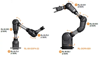
There are currently 6 different standard joints
1 – RL-50-PL1: strictly a pivot joint
2 – RL-50-TL1: strictly a rotating joint
3 – RL-50-001: a 2 axis joint with +/-90° pivot range ("THE classic")
4 – RL-50-002: a 2 axis joint with +130°/-50° pivot range ("asymmetric")
5 – RL-50-003: a 2 axis joint with +180°/0° pivot range ("fold-in motions")
6 – RL-90-BL1: Basic joint with 2 axis, ("larger and more powerful")
Custom versions of the joints are also available on request.
What angular positions are possible? Dead weights? Torque?
The following list provides more basic information. This table can also be found in our catalog.
| Ordering number | Number of ropes | Pivot angle | Rotation angle | Weight | Max. Load | ||||
|---|---|---|---|---|---|---|---|---|---|
| On-board drive | Optional feed-through | Standard (with stop dog) | Option (*without stop dog) | Standard (with stop dog) | Option (*without stop dog) | [gr] | Pivoting (Nm) | Rotating (Nm) | |
| 1. Pivoting joint RL-50-PL1 | 2 | 4 | 180° (±90°) | 210° (±105°) | - | - | 235 | 12 | - |
| 2. swivel joint RL-50-TL1 | 2 | 8 | - | - | 340° (±170°) | 540° (±270°) | 245 | - | 5 |
| 3. 2 axis joint RL-50-001 | 4 | 4 | 180° (±90°) | 210° (±105°) | 340° (±170°) | 540° (±270°) | 345 | 12 | 5 |
| 4. 2 axis joint RL-50-002 | 4 | 4 | 180° (+130°/-50°) | 240° (+135°/-105°) | 340° (±170°) | 540° (±270°) | 345 | 12 | 5 |
| 5. 2 axis joint RL-50-003 | 4 | 4 | 180 ° (+180°/0°) | 235° (+180°/-55°) | 340° (±170°) | 540° (±270°) | 400 | 12 | 5 |
| 6. Basic joint RL-90-BL1 | 4 | 8 | 180° (±90°) | 190° (±95°) | 180° (±90°) | - | 120 | 20 | 10 |
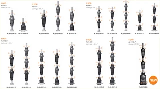
How can be joints be combined?
Each individual joint is equipped with draw wires. These must be guided through the joint respectively located underneath. This requirement restricts the available joint combinations. However, it is possible to combine individual articulated arms with 1 to 6 DOF, and to render a variety of kinematics. We will gladly advise you. The following diagram shows a possible combination - countless other options are available with the new RL-50-003 and RL-90-BL1 joint types!
What is meant by "Construction kit system"?
The underlying idea behind the Robolink construction kit is that our customers have access to individual (mechanical) components that can be used to build a robotic system. Depending on complexity and requirements, articulated arms can be configured and ordered with a range of complexities. igus® builds the arms as per customer specification and delivers ready-to-connect units. However, connecting individual joints ("as with LEGO®") is not possible.
Why is it not possible to simply reconfigure articulated arms without assistance?
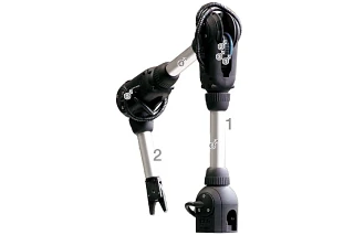
All joints are operated with draw wires. 2 wires are needed per degree of freedom (antagonistic principle). If the wires from the upper joint (2) were to be routed through the lower joint without a guide (1), the motion of the two joints would no longer be independent from each other. In order to achieve this independence, it is necessary to decouple the wire tension of the upper joint (2) from the motions of the lower joint (1). This is accomplished with a special Bowden cable system in the opening of the lower joint (see Figure). The wires then travel independently next to each other in the connecting tubes between the joints.
When ordering multi-axis systems from igus®, all Bowden cable system elements are pre-assembled, and the complete system is always delivered ready to install with all wires and tubes in the specified configuration.
- Pneumatic hose (gripper)
- 4 x Bowden cable system
- Sensor cable - joint 2
- 4 wires travel freely in the tube
- Individual Bowden cable system for the rotation
- 8 wires travel freely in the tube
What wire travel / forces are needed to move the joints?
The point of attack of the wires in the interior of the joint is defined by the size specification:
RL-50: Effective diameter: 50 mm (Rotating and pivot motion)
RL-90: Effective diameter: 90 mm (pivot motion), or 120 mm (rotating motion)
The wire travel on a RL-50 joint is therefore calculated as
π x d/4 ≈ 39 mm for an angular motion of 90°
π x d/2 ≈ 79 mm for an angular motion of 180°
The draw wire forces (depending on the applied torque) can be up to 600 N.
What is included in the delivered scope for a joint?
- Assembled joint, made from (PA 2200), incl. bearing locations (hard anodized aluminium = standard)
- Dyneema® wires
- Aluminium rods (standard = 100 mm respectively included, custom lengths on request)
- Angle sensors optional (-WS), 3 m sensor cable, assembled and tested. Wire nipple as connecting material, no charge based on consultation.
What is included in the delivered scope for an articulated arm?
- All joints pre-assembled as per item 7)
- all wires routed through with special Bowden segments as per item 5)
- Aluminium tubes between the joints, tailored to customer specification
- Mounting plate at the base of the arm
- Sensor cables routed through (option -WS), respectively 3 m of sensor cable assembled and tested. Wire nipple as connecting material, no charge based on consultation.
What is included in the delivered scope for a "complete system"?
Articulated joints as described in question 6), but with additional MIT drive unit, consisting of:
- igus® stepper motors, number corresponds to the number of axis in the arm
- Planetary gear for each motor
- "Drive wheel" to connect the wires to the drive
- "Tensioning tool" for convenient re-tensioning of the drive wheels
- Housings in which the motors are assembled, and on which the arm is built - in various configurations
everything completely assembled, pre-tensioned, and tested.
NOT included:
- Grippers (optionally available from igus®, other products can also be adapted)
- Control components
- Power cables (optionally available from igus®)
What angle sensors are in use?
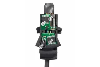
The joints are equipped (as option) with incremental angle sensors from Austriamicrosystems (AS5304A). Absolute encoders are currently not technically possible. The home position is defined with a Hall sensor that is respectively located in the center of the pivot or rotational range of the joint. This means that each joint must first be "homed" when power is supplied. More information about the sensor configuration and the cable routing can be found in our documentation.
The encoder resolution is (different between the joints!):
- 4,640 signals / 360° on all rotational motions of joint size RL-50
(29 pole pairs x 160 signals / pole pair) ≈ 0.078° - 4,960 signals / 360° on all pivot motions of joint size RL-50
(31 pole pairs x 160 signals / pole pair) ≈ 0.073° - 9,920 signals / 360° on all motions of joint size RL-90 ("Base")
(62 pole pairs x 160 signals / pole pair) ≈ 0.036
Standard sensors:
magnetic incremental angle sensors. The sensors have a resolution of ~0.07° per axis. All sensor units are ready for installation for the respective joints. Respectively incl. 3 m of sensor cable (6 cores per DOF)
- Hall sensor rotating motion
- Encoder rotating motion
- Encoder swivel motion
- Hall sensor rotating motion
Can articulated arms also be used in water?
Yes, the components consist primarily of plastics (PA2200), anodized aluminium, stainless steel (screws), Dyneema wires (PE), brass nipples. The sensors can be ordered in a sealed version (-SE = sealed encoder).


What drive versions are available?
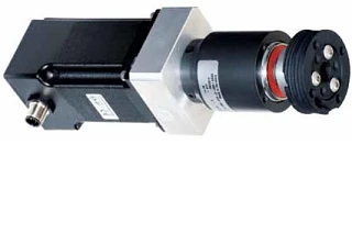
A wide range of drives can be used to move the wires. Options include manual drives ("crank"), pneumatics (e.g.: pneumatic muscle) or electrical motors (BLDC, DC, servo, linear, stepper motors). igus® provides stepper motors with planetary gears as an available drive option. Available options:
- NEMA23 stepper motor (strand or connector version) with 1:16 planetary gear
- NEMA17 stepper motor (strand or connector version) with 1:35 planetary gear
- stepper motor
- planetary gearbox
- tensionable drive wheel
How are Robolink articulated arms controlled or manipulated?
igus® does not develop, build, and sell control components. The available extent of a Robolink system is either the articulated arm or the articulated arm with "drive unit".
Control components must be provided or procured by the customer.
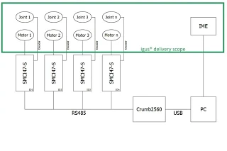
igus® has free control software for Robolink articulated arms with our stepper motors (open source). This is an easy to use, intuitive software platform to enter angle positions and to save simple motions. The software is not suited to interact with other systems. A contour control (or inverse kinematics) is not included. A specific hardware configuration is required to use the IME software (igus® motion editor). This essentially consists of the NANOTEC® stepper motor control (SMCI47-S2) and an ATmega Crumb2560 chip. The ATmega chip will be available from igus® during spring 2014 (currently at CHIP45 in the Internet). The following configurations are therefore needed:
What do I need to do to use the open source software IME (igus motion editor) from igus®?
The software is available as a free download. It is a graphical user interface that can be used to program and store simple motions. A contour control (or inverse kinematics) is not included.
What materials are in use?
Joints: Polyamide PA 2200 components, V2A screws, bearing rings made from hard anodized aluminium, alternatively: iglide® J or VA.
Connecting tubes: Anodized aluminium, alternatively: FGC or CFC.
Ropes:Dyneema® wires, brass end nipples.
What grippers can be used?
"Any conceivable" gripper can be combined with our articulated arms. Due to the relatively low total load-bearing capacity of the system, the grippers should be as light as possible. A wide range of light-weight pneumatic grippers are available, e.g. from SCHUNK, FESTO or FIPA. Frequently, the use of pneumatics is not desirable. Electrical grippers need to be used in this case Very light weight electrical grippers are available from GIMATIC, SCHUNK or SOMMER (however, these are all significantly more costly than simple pneumatic grippers). Since 2013, igus® has been offering simple plastic grippers, where the electrical motor is positioned in the Robolink tube. Gripper pads can also be optionally customized in this case.
What do joints or "systems" cost?
All prices for individual joints and systems can be found in our catalog. As a rule of thumb: a "complete system" with motors, gears, housing, joints, and sensors costs a little more than $1,200.00 per axis. E.g. approx. $7,200.00 for a 6 DOF system. An articulated arm WITHOUT motors (but with sensors) is approximately half (e.g. $600.00 / axis). Example:

