Change Language :
iglide® P210 - Material data
| General features | Unit | iglide® P | Test method |
|---|---|---|---|
| Density | g/cm³ | 1.40 | |
| Color | Yellow | ||
| Max. humidity absorption at 73°F/50% R. H. | % weight | 0.3 | DIN 53495 |
| Max. water absorption | % weight | 0.5 | |
| Coefficient of surface friction, dynamic, against steel | µ | 0.07 - 0.19 | |
| PV values max. (dry) | MPa x m/s | 0.4 |
| Mechanical properties | Unit | iglide® P | Test method |
|---|---|---|---|
| Bending E-module | MPa | 2.500 | DIN 53457 |
| Tensile strength at +68 °F | MPa | 70 | DIN 53452 |
| Compressive strength | MPa | 50 | |
| Maximum recommended surface pressure (68° F) | MPa | 50 | |
| Shore D hardness | 75 | DIN 53505 |
| Physical and thermal properties | Unit | iglide® P | Test method |
|---|---|---|---|
| Max. long term application temperature | °F | +212 | |
| Max. short term application temperature | °F | +320 | |
| Lower application temperature | °F | -40 | |
| Heat conductivity | [W/m x K] | 0.25 | ASTM C 177 |
| Coefficient of thermal expansion (at +73°F) | [K^(-1) x 10^(-5)] | 8 | DIN 53752 |
| Electrical properties | Unit | iglide® P | Test method |
|---|---|---|---|
| Specific forward resistance | Ωcm | > 10^12 | DIN IEC 93 |
| Surface resistance | Ω | > 10^11 | DIN 53482 |
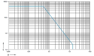
Figure 01: Permitted pv-values for iglide® P210 bearings with 1 mm wall thickness in dry operation against a steel shaft, at +68°F, installed in a steel housing.
X = Sliding speed [m/s]
Y = Load [MPa]
iglide® P210 plain bearings provide users with versatile all-round bearings, which have demonstrated above average service life, primarily in pivot applications at medium loads of up to 20 MPa.
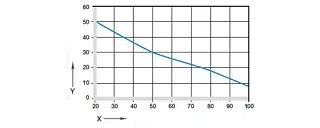
Figure 02: Maximum recommended surface pressure dependent on the temperature (50 MPa to +20 °C)
X = Temperature [°C]
Y = Load [MPa]
Mechanical properties
Maximum recommended surface pressure represents a mechanical material parameter. Tribological conclusions cannot be drawn from it. With increasing temperatures, the compressive strength of iglide® P210 plain bearings decreases. Fig. 02 clarifies this connection.
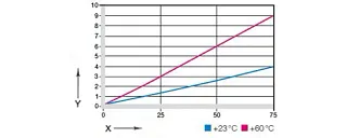
Figure 03: Deformation under load and temperatures
X = Load [MPa]
Y = Deformatio [%]
Fig. 03 shows the elastic deformation of iglide® P210 during radial loading. Under the maximum recommended surface pressure of 50 MPa, the deformation at room temperature amounts to less than 3 %.
Permitted surface speeds
Plain bearings made of iglide® P210 are maintenance-free bearings developed for low to medium surface speeds. The maximum values stated in the Table 02 can be attained only with very low surface pressure. The specified maximum speed is the speed at which the long-term permitted temperature is reached by an increase in heat through friction.
| m/s | Rotary | Oscillating | Linear |
|---|---|---|---|
| Constant | 1 | 0.7 | 3 |
| Short-term | 2 | 1.4 | 4 |
Temperatures
With its extreme long-term application temperature of +212°F, iglide® P210 is suitable for a wide range of applications. If still higher temperatures are required, the best-seller iglide® G with 266°F upper long-term temperature is available. The temperatures prevailing in the bearing system also have an influence on the bearing wear. Rising temperatures mean higher wear. An additional securing is recommended at temperatures higher than +122°F.
| iglide® P | Application temperature |
|---|---|
| Lower | -40°F |
| Upper, long-term | +212°F |
| Upper, short-term | +320°F |
| Secure axially in addition | +122°F |
Friction and wear
Just like the wear resistance, the coefficient of friction µ also alters with the load (Fig. 04 and 05).
| iglide® P | Dry | Grease | Oil | Water |
|---|---|---|---|---|
| Coefficients of friction µ | 0.08 - 0.23 | 0.09 | 0.04 | 0.04 |


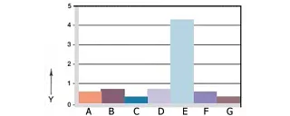
Figure 06: Wear, rotating application with different shaft materials, p = 1 MPa, v = 0,3 m/s
X = shaft materials
Y = wear [μm/km]
A = Aluminum, hard-anodized
B = machining steel
C = Cf53
D = Cf53, hard chrome-plated
E = St37
F = V2A
G = X90
Shaft materials
Figure 06 displays a summary of the results of tests with different shaft materials, which were conducted with iglide® P210 plain bearings. In rotating movements below 1 MPa radial load, the wear of iglide® P210 is generally very low. The wear is significantly higher only in combination with St37 shafts. In general, the wear during rotation is higher than for a swivel application with the same load. This reverses only from loads of 25 MPa (Fig. 07).
Material resistance
Chemical resistance
iglide® P210 bearings have a good resistance against chemicals. They are resistant to most lubricants. iglide® P210 is not affected by most weak organic and inorganic acids.
Radioactive rays
Bearings made of iglide® P210 are conditionally usable under radioactive radiation. They are resistant up to a radiation intensity of3 x 10² Gy.
UV-resistant
iglide® P210 plain bearings have comparatively good UV resistance.
Vacuum
The existent humidity of iglide® P210 bearings degasses in the vacuum. The use in vacuum is possible only limited.
| Medium | Resistance |
|---|---|
| Alcohols | + |
| Hydrocarbons | - |
| Greases, oils without additives | + |
| Fuels | + |
| Diluted acids | 0 |
| Strong acids | - |
| Diluted bases | - |
| Strong bases | - |
| + resistant 0 conditionally resistant - non-resistant | |
| All specifications at room temperature[+68°F] Table 05: Chemical resistance of iglide® P |
Electrical properties
iglide® P bearings are electrically insulating.
| Specific forward resistance | Surface resistance |
|---|---|
| > 10^12 Ωcm | > 10^11 Ω |
Moisture absorption
The humidity absorption of iglide® P210 bearings amounts to about 0.3 Wt.-% in standard climatic conditions. The saturation limit in water is 0,5 %. This minor humidity absorption is clearly below the values of iglide® G.
| Maximum moisture absorption | |
|---|---|
| by +73 °F/50 % r. F. | 0,3 Wt.-% |
| Max. water absorption | 0,5 Wt.-% |
| Table 06: Moisture absorption |
Installation tolerances
iglide® P210- bearings are standard bearings for shafts with h-tolerance (recommended minimum h9). The bearings are designed for press-fit in a housing with h7 tolerance. After the installation in a housing with nominal diameter, the inner diameter of the bearing automatically adjusts to the E10 tolerance. In certain dimensions the tolerance in dependence on the wall thickness deviates from this (See delivery program )
| Diameter d1 [mm] | Shaft h9 [mm] | iglidur® P210 E10 [mm] | Housing H7 [mm] |
|---|---|---|---|
| Up to 3 | 0 - 0,025 | +0,014 | 0 +0,010 |
| > 3 to 6 | 0 - 0,030 | +0,020 | 0 +0,012 |
| > 6 to 10 | 0 - 0,036 | +0,025 | 0 +0,015 |
| > 10 to 18 | 0 - 0,043 | +0,032 | 0 +0,018 |
| > 18 to 30 | 0 - 0,052 | +0,040 | 0 +0,021 |
| > 30 to 50 | 0 - 0,062 | +0,050 | 0 +0,025 |
| > 50 to 80 | 0 - 0,074 | +0,060 | 0 +0,030 |
| > 80 to 120 | 0 - 0,087 | +0,072 | 0 +0,035 |
| > 120 to 180 | 0 - 0,100 | +0,085 | 0 +0,040 |
| Table 07: Important tolerances iaw. ISO 3547-1 after press-fitting |