Change Language :
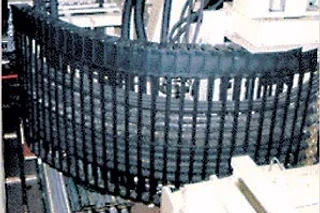
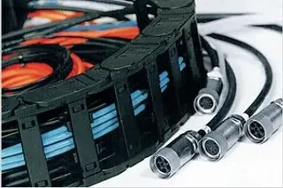
Cable and hose packages
Hydraulics and electric cables are separated from one another in this example
General rules for cables and hoses in energy chains
The key advantage of igus® energy chain cable carriers is the safe guidance of energy and data in one system. We will recommend the optimal separation layout of conduits within an energy chain, but you, the customer, are still afforded the final choice. It is possible, for instance, to maintain minimum distances between bus and motor cables. You can mix pneumatics, electric and hydraulics in the same compartments. In addition to the quality of the cables used, the arrangement of each conduit within the energy chain and the space allowed, are important for the service life of the system. Various separation options enable the adaptation of the energy chains to the specific requirements of each respective application. In this chapter, we give you detailed recommendations. Due to the variety of the application parameters, we strongly recommend you take advantage of our free consultation services. Simply give us a list of your cable requirements (or merely the required electrical or other services) and you will receive our recommendation by the end of the next business day.
Neatly laid cables with igus® interior separation
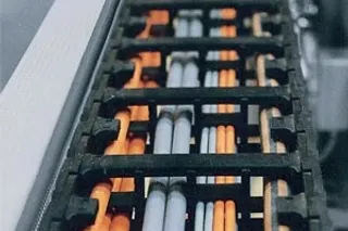
Neatly laid cables with igus® interior separation
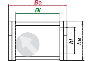
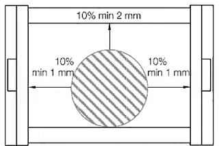
Maximum cable and hose diameters
The maximum cable and/or hose diameter corresponds to the inner height of the selected energy chain/E-Tube, with additional minimum clearance. This minimum clearance would be, for example, 10% for electrical round cables, 20% for hydraulic hoses. An energy chain is ideal if a minimum lateral gap to the next cable or hose has been factored in. Depending on the nature of the cables, the dynamics, and the expected service life, more clearance must be allowed. In specific cases, clearances may be altered further. Please consult igus.
Modular energy chain systems solves all known requirements for interior separation
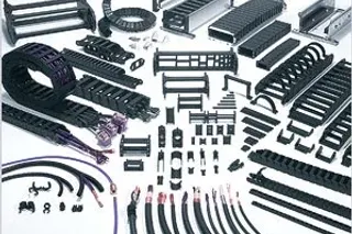
Modular energy chain systems solves all known requirements for interior separation
E- Chain®-Distribution
Cables and hoses with very different diameters should be laid separately. The separation is achieved using modular separators. Cables and hoses must under no circumstances have the opportunity to tangle. Therefore, the clearance height of a compartment with several similar cables or hoses next to one another must not amount tomore than one and a half times the cable/hose diameter.
The maximum cable diameter is stated for every series in the respective section
Electric cables require a minimum of 10% of space reserve around, and hydraulic hoses 20%
Rules for:
- Maximum output meter
- Separation
- Bending radius
Distribution rules
Reasons for distribution rules: The cables and hoses must be laid so that they can move freely at all times and so that no tensile force is exerted at the radius of the energy chain cable carriers. For high-speed applications and high cycles, cables or hoses must not be laid on top of each other without horizontal separation. The standard values for this are: Travel speed over 0.5 m/s and cycles over 10,000 p.a. igus® interior separation offers a safe solution for this situation.

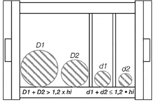
Distribution rules:
- D1 + D2 > 1,2 x hi
- Rule 1 - If D1 + D2 > 1.2 x EChain® inner height, no separation between the two cables/-hoses is necessary. Two cables/hoses should never be left unguided on top of one another or be allowed to become tangled.
- d1 + d2 ≤ 1,2 x hi
- Rule 2: If d1 + d2 ≤ 1.2 x EChain® inner height, a vertical separator or a horizontal shelf must be used to reduce the inner height. Thereby preventing the entanglement of d1 and d2.
Space reserve "around" electric round cables
Further guidelines for distribution
The cable or hose weight should be symmetrically distributed along the width of the energy chain. Cables and hoses with different outer jacket materials mustnot be allowed to "stick" together. If necessary, they must be laid separately. All igus® chainflex® cables can be combined with each and other brands of cable or hose. The cables and hoses should always be fixed at the moving end. The fixed end should always involve strain relief. Exceptions are made only for certain hydraulic hoses with length compensation issues or other high pressure hoses (i.e. hydraulic hoses). Generally, the faster and more frequently the energy chain operates, the more important the exact positioning of the cables and hoses inside the chain. Due to the wide variety of the possibilities, we strongly recommend you take advantage of our free consultation services for your specific applications.
Bending radius R
The bending radius of our energy chain cable carrier depends on the "thickest" or "stiffest" cable or hose in your application. The bending radii of the E- Chain® cable carriers should be adjusted to the recommendations of the cable or hose manufacturer. The selection of a larger radius than the minimum will positively affect service life. The specification of minimum bending radii for cables and hoses refers to use at normal temperatures. Other bending radii may be recommended.
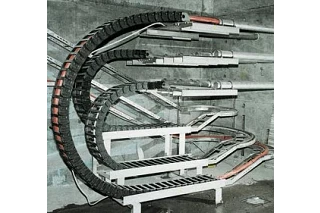
We recommend complete energy chain systems - where bending radii for all cables and hoses, interior separation and service life are optimally matched.
The igus® program offers up to to 12 different bending radii from stock - here the "Storbaelt-Bridge-Project"
All-around clearance space in % for various cables/hoses
- Electrical round cables: 10%
- Electrical flat cables: 10%
- Pneumatics: 5-10%
- Hydraulics: 20%
- Media hoses: 15-20%
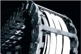
With igus® energy chain system, corkscrewing belongs to the past
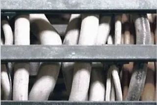
With igus® energy chain system, corkscrewing belongs to the past
Round electrical cables
For electrical cables, the round cable is a safe, modular and cost-effective solution for energy chain systems. We recommend the following criteria for selecting the proper round electrical cables:
- Small minimum bending radii and mounting heights
- Long service life at minimum bending radius
- Service life expectations for your application (short or long travel, hanging, etc.)
- Test data on service life from realistic tests
- Uncomplicated installation process - no hanging, laying out, etc.
- Strain relief integrated directly into the mounting bracket
- Flexible shields for shielded cables
- Abrasion-resistant and non-adhesive outer jackets
- Large selection to avoid expensive custom designs.
For bus cables and fiber optic cable, special attention must be paid to how effective transmission rates and shielding remain after millions of cycles at the minimum bending radius.
Installation and strain relief of round electrical cables
The cables must be laid straight, without twisting. Cables must not be uncoiled from the top of the spool. igus® chainflex® cables are immediately ready for placement directly into the EChain®. They need not be disconnected or laid out before installation.
- The cables must be laid so that each individual cable can move freely from side to side.
- The cables must be able to move freely along the radius. This must be double-checked if the upper run operates at the cable’s maximum bending radius.
- The division of the E-Chain’s® interior using shelves or igus® interior separators is necessary if several cables and/or hoses with varying diameters are laid out. It is important to prevent cables and hoses from tangling.
- For cables and hoses with different jacket materials, it is important to prevent them from "sticking" to one another. If necessary, they should be separated. igus® chainflex® cables can be combined with all others.
- Round electrical cables must be secured with strain relief at both ends. In exceptional cases, the cables may be fixed with strain relief at the moving end of the energy chain only. A gap of 10-30 x cable diameter between the end of the bending segment and the fixed point is recommended for most cables. chainflex® cables can, on the other hand, be secured directly to the mounting bracket with strain relief (this has been confirmed with testing).


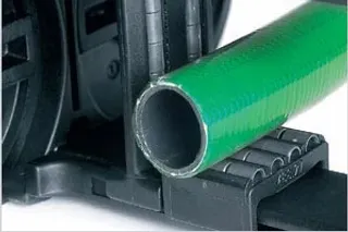
Fully pre-assembled energy chain system with several pneumatic hoses
Pneumatic hose
In principle, the same rules apply for pneumatic hoses as for round cables. In practice, it has been demonstrated that pneumatic hoses are less susceptible to wear. After consultation, they can be laid together more closely than the "10% clearance all-around" rule. A double-sided strain relief is required under these conditions. For pneumatic hoses made of rubber, we recommend strictly following the "10% clearance" rule because they tend to adhere to each other and to other conduits.
The igus® program also offers polymer pneumatic hoses called: "chainflex® Air"
Flat cables and pneumatic hoses installed in an energy chain with full interior separation
Flat cables
Flat cables must be able to move freely along the bending radius. Two flat cables next to one another should be kept apart with separators. If two flat cables are laid on top of one another, we strongly recommend the use of horizontal igus® shelving. Flat and round cables should be laid separately in the energy chain. Strain relief should be attached at both ends. Flat cables are only conditionally recommended for use in energy chains.
Outer jackets made of rubber must be specified particularly carefully, because of potentially high static friction.
igus® energy chains with hydraulic hoses in a tree-stripping machine
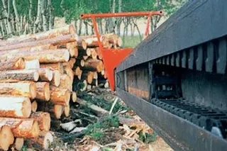
Hydraulic hoses need more space: 20% all-around clearance
When designing hydraulic hoses in energy chains, special attention should be paid to the expansion of the hoses when pressurized. Sufficient room must be left in the energy chain It is important for selected hoses to be sufficiently flexible (i.e. meet bending radius specified by the energy chain). The gliding ability and abrasion-resistant surface of the hoses are also important. All crossbars and shelves in the igus® energy chain minimize abrasion of hoses through wide, rounded and smooth surfaces. Normally, hoses with textile braiding are more flexible than hoses made of steel wire. As lateral movements of the hydraulic hoses within the energy chain can lead to increased abrasion of the hose material, they should be secured in position with vertical separators, but not forced. Special "locking" separators, which grip the opening crossbars of the chain, as well as the use of "spacers," prevent lateral shifting of the separators - they also ensure the hoses stay put in cases of strong vibration and impact on the chain.
igus® Rollclip, detachable
Strain reliefs
Hydraulic hoses are most often stretched lengthwise during operation. This must be taken into account when applying strain relief. More hose length is factored in to allow the hose to "breathe", or "floating" strain relief must be implemented. In some cases, one-sided strain relief on the moving end can be tolerated.
Rollclip
In almost all cases, the broad, smooth and rounded surfaces of all igus® energy chains are sufficient to protect hydraulic hoses from abrasion. In extreme cases, the igus® Rollclip can be installed. The hoses come in contact with a series of polymer cylinders which rotate. "Extreme" cases include particularly soft materials, particularly narrow bending radii or highly dynamic loads. Over 95% of all applications can be solved without Rollclips.
Contact Us
Questions or product information? Please contact:

Customer Service
Customer Service:
Phone: Monday to Friday from 8 am - 8 pm
LiveChat: 24 hours
Book a Call
Book an Appointment with a Product Expert