Inquiry / Contact
igus® inc.

PO BOX 14349

East Providence

RI 02914

+1 800 521 2747
+1 401 438 7270
US(EN)

drylin® T - Mounting Version - Horizontal

1st Step:

Select the mounting version:

1 rail and 1 carriage

1 rail and 2 carriages

2 rails and 4 carriages

2nd Step:

Check to see whether the maximum clearances of the applied forces are within the permissible values (see maximum permissible clearances, right).

Maximum permitted clearances:

Option: 1 rail, 1 carriage
sy + sz < 2 Lx - Y0
ay + az < 2 Lx - Y0
sy < 5 Zm
sz < 5 Zm

3rd Step:

Calculate the necessary driving force

3.1

Center of gravity in x- and z-direction inside the carriage(s)

3.2

Center of gravity in z direction outsideof the carriage(s)

3.3

Center of gravity in x direction outside of the carriage(s)
If the position of the center of gravity is not specified: Fa = MAX (Fa1, Fa2, Fa3)


4th Step:

Calculate the maximum bearing load

4.1

Maximum bearing load in y direction

4.2

Maximum bearing load in z direction


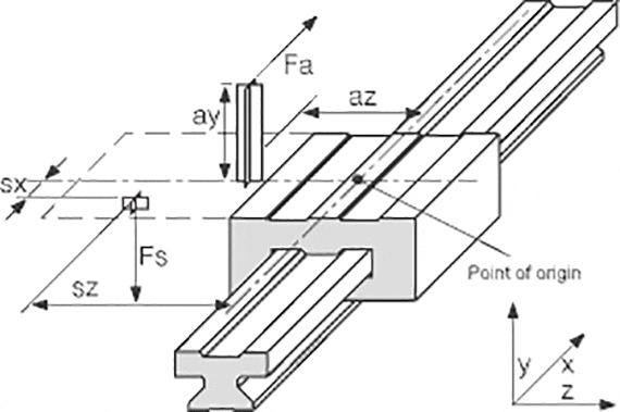
Variables in the calculation:

Fa: Driving power [lbs]
Fs: Mass force [lbs]
Fy, Fz: Bearing load in y- or z-direction [lbs]
sx, sy, sz: Clearance of the mass force
in x-, y- or z-direction
[mm]
ay, az: Clearance of the driving power
in y- or z-direction
[mm]
wx: Clearance of the carriage on a rail [mm]
LX: Constant based on the installation size [mm]
Zm: Constant based on the installation size [mm]
Y0: Constant based on the installation size [mm]
b: Clearance of the guide rails [mm]
µ: Coefficient of friction,
µ = 0 in static loads,
µ = 0.2 in dynamic loads
 
ZW: Number of carriages per rail  


The constant values:

Order no. LX ZM Y0
  [mm] [mm] [mm]
TW-01-15 29 16 11.5
TW-01-20 35 23 15.0
TW-01-25 41 25 19.0
TW-01-30 49 29 21.5


Coefficients:

  1 rail,
1 carriages
K1 |(ay+Y0)/Lx|
K2 (sy+Y0)/Lx
K3 |az/Lx|
K4 |sx/Lx|
K5 sz/Lx
K6 |(sy+Y0)/Zm|
K7 |sz/Zm|

5th Step:

Check calculated load for both y and z with the Maximum Permissible Load table for Fymax and Fzmax (right). This table illustrates the maximum permissible load on a single gliding element from the DryLin T carriage. Evaluating the maximum load on a single gliding element establishes a safety factor for the linear system.

Maximum permitted load:


[lbs
Order no. Fymax, Fzmax[N]
TW-01-15 450
TW-01-20 830
TW-01-25 1125
TW-01-30 1575

6th Step:

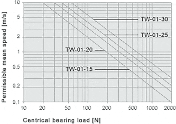
Determine the maximum permissible speed for the calculated load from Step No. 4
Diagram for the determination of the maximum permitted speed for the determined bearing load


The terms "igus", "Apiro", "chainflex", "CFRIP", "conprotect", "CTD", "drylin", "dry-tech", "dryspin", "easy chain", "e-chain", "e-chain systems", "e-ketten", "e-kettensysteme", "e-skin", "e-spool", "flizz", "ibow", "igear", "iglidur", "igubal", "kineKIT", "manus", "motion plastics", "pikchain", "plastics for longer life", "readychain", "readycable", "ReBeL", "speedigus", "triflex", "robolink", "xirodur", and "xiros" are legally protected trademarks of the igus® GmbH/ Cologne in the Federal Republic of Germany and where applicable in some foreign countries.

igus® GmbH points out that it does not sell any products of the companies Allen Bradley, B&R, Baumüller, Beckhoff, Lahr, Control Techniques, Danaher Motion, ELAU, FAGOR, FANUC, Festo, Heidenhain, Jetter, Lenze, LinMot, LTi DRiVES, Mitsibushi, NUM,Parker, Bosch Rexroth, SEW, Siemens, Stöber and all other drive manufacturers mention in this website. The products offered by igus® are those of igus® GmbH

igus inc headquarters is located at 257 Ferris Ave, Rumford, RI 02916. igus enjoyneering center is located at 2055 Franklin Rd, Bloomfield Twp, MI 48302