Change Language :
iglide® A181 - Material data
| General features | Unit | iglide® A181 | test method |
|---|---|---|---|
| Density | g/cm3 | 1,38 | |
| Color | blue | ||
| Max. humidity absorption at 73°F/50% R. H. | % weight | 0,2 | DIN 53495 |
| Max. water absorption | % weight | 1,3 | |
| Coefficient of surface friction, dynamic, against steel | µ | 0,10-0,21 | |
| pv values (dry) | MPa x m/s | 0,31 | |
| Mechanical properties | |||
| Bending E-module | MPa | 1.913 | DIN 53457 |
| Tensile strength at +68°F | MPa | 48 | DIN 53452 |
| Compressive strength | MPa | 60 | |
| Maximum recommended surface pressure (68° F) | MPa | 31 | |
| Shore D-hardness | 76 | DIN 53505 | |
| Physical and thermal properties | |||
| Max. long term application temperature | °F | +194 | |
| Max. short term application temperature | °F | +230 | |
| Minimum application temperature | °F | -58 | |
| thermal / heat conductivity | [W/m x K] | 0,25 | ASTM C 177 |
| Coefficient of thermal expansion (at 73° F) | [K-1 x 10⁻⁵] | 11 | DIN 53752 |
| Electrical properties | |||
| Specific forward resistance | Ωcm | < 1012 | DIN IEC 93 |
| Surface resistance | Ω | < 1012 | DIN 53482 |
| Table 01: Material properties |
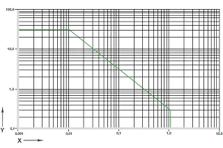
Fig. 01: Permitted PV values for iglide® A181 plain bearings with 1 mm wall thickness in dry-running operation against a steel shaft, at +20°C, installed in a steel housing
X = gliding speed [m/s]
Y = load [MPa]
Due to their technical characteristics and compliance with applicable regulations, iglide® A181 plain bearingsare predestined for use in food technology applications. Directly comparable to iglide® A180 with respect to temperature and media resistance, iglide® A181 represents yet another improvement with respect to wear resistance in most applications.
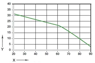
Figure 02: Maximum recommended surface pressure dependent on the temperature (31 MPa to +20 °C)
X = Temperature [°C]
Y = Load [MPa]
Mechanical properties
With increasing temperatures, the compressive strength of iglide® A181 plain bearings decreases. Fig. 02 clarifies this connection. Maximum recommended surface pressure represents a mechanical material parameter. Tribological conclusions cannot be drawn from it.
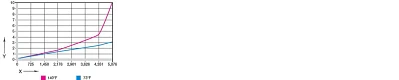
Figure 03 shows the elastic deformation of iglide® A181 with radial loads.
Permitted surface speeds
iglide® A181 is developed for low surface speeds. Maximum speeds up to 0.8 m/s (rotating) and 3.5 m/s (linear) respectively are permitted for continuous application in dry operation. The values specified in Table 02 state the limits to which the long-term permitted temperature rises due to friction heat. In practice these limit values are not always reached due to interactions.
| m/s | Rotary | Oscillating | Linear |
|---|---|---|---|
| Constant | 0,8 | 0,6 | 3,5 |
| Short-term | 1,2 | 1,0 | 5,0 |
| Table 02: Maximum surface speed |
Temperatures
The upper long-term application temperature of +194°F allows for a variety of applications in the food industry. As Fig. 02 shows, the compressive strength decreases with increasing temperatures. The additional friction heat in the bearing system should be considered in the temperature observations. An additional securing is recommended at temperatures higher than +140°F.
| iglide® A181 | Application temperature |
|---|---|
| Lower | - 58 °F |
| Upper, long-term | + 194 °F |
| Upper, short-term | + 230 °F |
| Secure axially in addition | + 140 °F |
| Table 03: Temperature limits |
Friction and wear
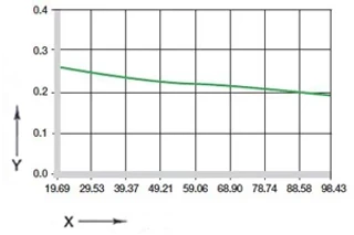
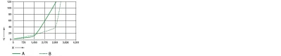
Coefficient of friction and wear resistance alter with the application parameters(Fig. 04 and 05). In the iglide® A181 plain bearings, the alteration of the friction coefficient µ dependent on surface speed and the shaft's surface finish is only negligently pronounced.
| iglide® A181 | Dry | Grease | Oil | Water |
|---|---|---|---|---|
| Coefficients of friction µ | 0,10-0,21 | 0,08 | 0,03 | 0,04 |
| Table 04: Coefficients of friction against steel (Ra = 1µm, 50 HRC) |
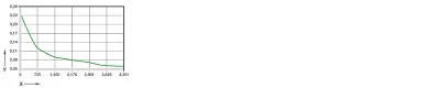
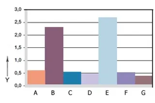
Figure 06: Wear, rotating application with different shaft materials, p = 1 MPa, v = 0,3 m/s
X = Shaft material
Y = Wear [μm/km]
A = Aluminum, hard-anodized
B = machining steel
C = Cf53
D = Cf53, hard chrome-plated
E = St37
F = V2A
G = X90
Shaft materials
Figure 06 displays a summary of the results of tests with different shaft materials, which were conducted with iglide® A181 plain bearings. Special emphasis is given to the corrosion-resistant shaft types in the food industry. Fig. 06 shows that low wear rates can be achieved especially in combination with these shafts. As in many iglide® materials, the wear rate increases in rotation with otherwise identical parameters (Fig. 07).
Chemical resistance
iglide® A181 bearings can be used under various environmental conditions and in contact with numerous chemicals. Table 05 gives an overview of the chemical resistance of iglide® A181 bearings at room temperature.
| Medium | Resistance |
|---|---|
| Alcohols | + |
| Hydrocarbons | + |
| Greases, oil without additives | + |
| Fuels | + |
| Diluted acids | 0 to - |
| Strong acids | - |
| Diluted bases | + |
| Strong bases | + to 0 |
| + resistant | 0 limited resistance | - unresistant | |
| All specifications at room temperature [+20°C] | |
| [bTable 05: resistant to chemicals[/b] |
Radioactive rays
iglide® A181 bearings are radiation resistant up to a radioactive intensity of 2 · 10² Gy.
UV-resistant
iglide® A181 bearings are permanently resistant against UV rays.
Vacuum
In application in vacuum, the potentially existent moisture content is degassed. For this reason only dry bearings are suitable for vacuum.
Electrical properties
| Specific forward resistance | Surface resistance |
|---|---|
| < 1012 Ωcm | < 1012 Ω |
| iglide® A181 bearings are electrically insulating. |
Moisture absorption
The iglide® A181 bearings absorb up to 0.2% water through atmospheric humidity (+73°F, 50% relative atmospheric humidity), when saturated with water they absorb 1.3%.
| Maximum moisture absorption | |
|---|---|
| by +73 °F/50 % r. F. | 0,2 weight-% |
| Max. water absorption | 1,3 weight-% |
| Table 06: Moisture absorption |
Installation tolerances
iglide® A181- bearings are standard bearings for shafts with h-tolerance (recommended minimum h9). The bearings are designed for press-fit in a housing with h7 tolerance. After the installation in a housing with nominal diameter, the inner diameter of the bearing automatically adjusts to the E10 tolerance.
| Diameter d1 [mm] | Shaft h9 [mm] | iglide® A181 F10 [mm] | Housing H7 [mm] |
|---|---|---|---|
| Up to 3 | 0 - 0,025 | +0,014 +0,054 | 0 +0,010 |
| > 3 to 6 | 0 - 0,030 | +0,020 +0,068 | 0 +0,012 |
| > 6 to 10 | 0 - 0,036 | +0,025 +0,083 | 0 +0,015 |
| > 10 to 18 | 0 - 0,043 | +0,032 +0,102 | 0 +0,018 |
| > 18 to 30 | 0 - 0,052 | +0,040 +0,124 | 0 +0,021 |
| > 30 to 50 | 0 - 0,062 | +0,050 +0,150 | 0 +0,025 |
| > 50 to 80 | 0 - 0,074 | +0,060 +0,180 | 0 +0,030 |
| > 80 to 120 | 0 - 0,087 | +0,072 +0,212 | 0 +0,035 |
| > 120 to 180 | 0 - 0,100 | +0,085 +0,245 | 0 +0,040 |
| Table 07: Important tolerances iaw. ISO 3547-1 after press-fitting |