Inquiry / Contact
igus® inc.

PO BOX 14349

East Providence

RI 02914

+1 800 521 2747
+1 401 438 7270
US(EN)

Continuous-flex Cable Construction

The Bundling Versus Layering Technique

Flexible cables constructed in layers are significantly cheaper to produce, therefore many manufacturers offer cables with this low-cost design. However, such flexible cables are often constructed without attention to pitch length, pitch direction or center-filling material and typically have fleece wraps and binders with a tube-extruded jacket.

These types of cables may provide sufficient support in certain short-travel applications. However, in a long-travel, gliding or demanding-flex application, they tend to fatigue and their insulation and jacket compounds lose their tensile and elongation properties. This greatly reduces service life. As these materials break down, the flexible cable core is compromised and the torsional forces of the cabled conductors release and untwist in parts of the cable. This causes a 'corkscrew' effect (Figure 1).
Corkscrewed flexible cable Figure 1: 'Corkscrew' refers to the permanent deformation of flexing cables in automated applications and is caused by excessive stressing. The end result is usually core ruptures, cable failure, and machine downtime.
The risk of such problems is increased with flexible cables with multiple layers (usually more than 12 conductors).

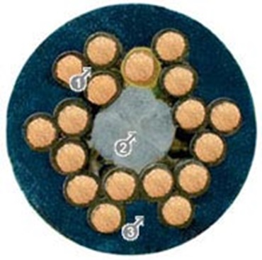
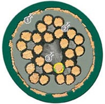
In the majority of igus®' chainflex® 'continuous-flex' cables, the conductors are bundled rather than layered to eliminate these problems (Figures 2 & 3). The wires are twisted with a special pitch length and the resulting conductors are cabled into bundles. For large cross sections, they are twisted around a strain relief element. The conductors are then bundled around a tension-proof center.

The multiple bundling of the conductors changes the inner radius and outer radius of the bent cable several times at identical intervals as it flexes. Pulling and compressive forces balance one another around the highly-tensile center cord, which provides the necessary inner stability. As a result, the cable core remains stable even under maximum bending stress.
Wire and core structures of a Chainflex® continuous-flex cable Figure 2: Wire and core structures of a chainflex® continuous-flex cable: 1. Single wire bundles with short pitch lengths 2. Tension-proof center element 3. Highly abrasion-resistant, gusset-filling extruded jacket.
Continuous-flex cable Figure 3: igus® continuous-flex cable with stranding in bundles around a center cord: 1. Total shield with optimized braiding angle. 2. Gusset-filling extruded inner jacket. 3. Tension-proof center element.

Useful Links


Application Assistance

For further questions or product information, please contact:

Photo
Don Nester

Chainflex® Product Manager

Email

Customer Service:

Monday to Friday from 8 am - 8 pm

Online:

24h


The terms "igus", "Apiro", "chainflex", "CFRIP", "conprotect", "CTD", "drylin", "dry-tech", "dryspin", "easy chain", "e-chain", "e-chain systems", "e-ketten", "e-kettensysteme", "e-skin", "e-spool", "flizz", "ibow", "igear", "iglidur", "igubal", "kineKIT", "manus", "motion plastics", "pikchain", "plastics for longer life", "readychain", "readycable", "ReBeL", "speedigus", "triflex", "robolink", "xirodur", and "xiros" are legally protected trademarks of the igus® GmbH/ Cologne in the Federal Republic of Germany and where applicable in some foreign countries.

igus® GmbH points out that it does not sell any products of the companies Allen Bradley, B&R, Baumüller, Beckhoff, Lahr, Control Techniques, Danaher Motion, ELAU, FAGOR, FANUC, Festo, Heidenhain, Jetter, Lenze, LinMot, LTi DRiVES, Mitsibushi, NUM,Parker, Bosch Rexroth, SEW, Siemens, Stöber and all other drive manufacturers mention in this website. The products offered by igus® are those of igus® GmbH

igus inc headquarters is located at 257 Ferris Ave, Rumford, RI 02916. igus enjoyneering center is located at 2055 Franklin Rd, Bloomfield Twp, MI 48302