Order no. | Bi [mm] |
Ba [mm] |
hi [mm] |
ha [mm] |
R [mm] |
||
---|---|---|---|---|---|---|---|
MF-06-10-018 | 0.39 | 0.75 | 0.43 | 0.67 | Upon request |
further dimensions | |
---|---|
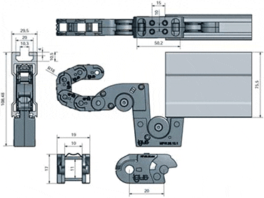
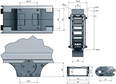
Installation height for the complete system: | 108,48 mm |
Installation width of the complete system: | 29,5 mm |
Recommended length of the trough sections: | 2.0 m, 3.0 m and 6.0 m - Material: Aluminum die-casting |
Maximum cable/hose outer diameter: | Ø 8 mm |
Order no. | Bi [mm] |
Ba [mm] |
hi [mm] |
ha [mm] |
R [mm] |
||
---|---|---|---|---|---|---|---|
MF-08-18-035 | 0.71 | 1.14 | 0.51 | 0.83 | Upon request |
further dimensions | |
---|---|
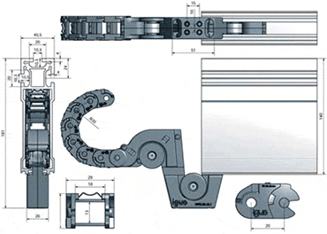
Installation height for the complete system: | 161 mm |
Installation width of the complete system: | 40,5 mm |
Recommended length of the trough sections: | 2,0 m, 3,0 m and 6,0 m - Material: Aluminum die-casting |
Maximum cable/hose outer diameter: | Ø 9,5 mm |
Order no. | Bi [mm] |
Ba [mm] |
hi [mm] |
ha [mm] |
R [mm] |
||
---|---|---|---|---|---|---|---|
MF-10-50-075 | 1.97 | 2.48 | 0.79 | 1.08 | Upon request |
further dimensions | |
---|---|
Installation height for the complete system: | 275 mm |
Installation width of the complete system: | 107,6 mm |
Recommended length of the trough sections: | Standard trough pieces 2 m length, anodised aluminium extruded profile |
Maximum cable/hose outer diameter: | Ø 16 mm |
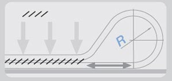
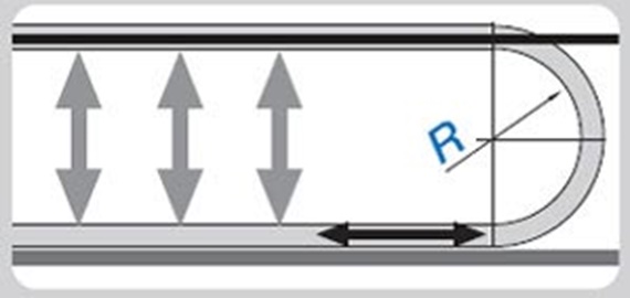
Separate upper and lower runs on the flizz® e-chain®,
hence less friction and reduced power consumption in motion
"Wings" firmly hold the e-chain® in the guide channel
3Plastic spring enables the e-chain® to roll softy in the flizz® channel, thereby significantly reducing the noise
4Integrated strain relief in the carriage for secure fixing of the cables
5Universal connection through three T-slots possible
6The e-chain® is fastened at the moving end via the moving end carriage
7Usable in the counter direction, which means double filling or two separate travels is possible
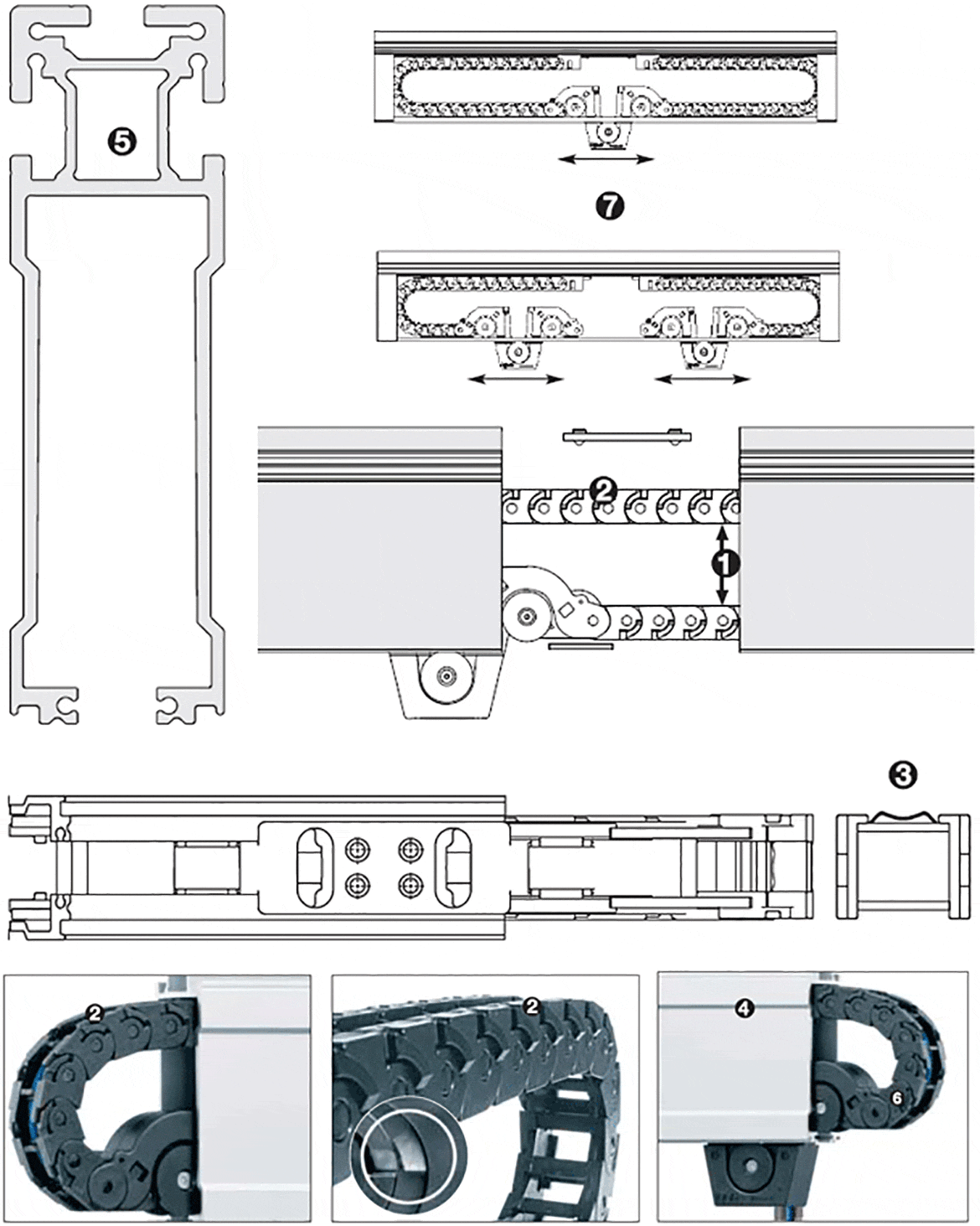
Separate upper and lower runs: wings fold in in the radius. e-chain® glides freely
Fold out in the extended condition, the e-chain® firmly holds in the Micro flizz® guide channel
Energy, data, pneumatics in the smallest space. chainflex® cables are optimally designed for this application
Polymer spring dampens the rolling noise of the e-chain® in the flizz® channel - thus minimizes noise emission
Micro flizz® accessories: Moving end
connector for compressed air coupling
Potential application area for the micro flizz®: Storage and retrieval units, indoor cranes, etc.
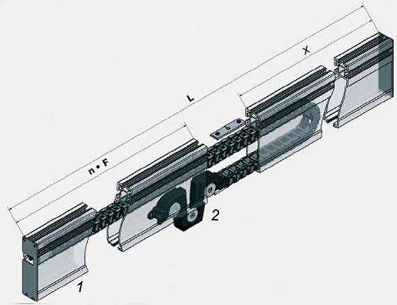
Micro flizz® as an end infeed version with a total length of 5000 mm, distributed over 2 channels of 2000 mm each and 1 channel with a residual length of 1000 mm
Bi = e-chains® internal width
R = bending radius [mm]
n= number of channel pieces
S = travel distance = L- 300[mm]
F = field length [mm]
L = total length [mm]
X = remaining length [mm]
MF.06.10.018.5000/2000 Version MF06
MF.08.18.035.5000/2000 Version MF08
MF.10.50.075.5000/2000 Version MF08
MF = Micro flizz® End infeed
06./08.10 = Version(Series)
10./18.50 = e-chains® Inner width
018./035./075 = Bending radius [mm]
5000/2000 = total length / field length [mm]
This is how you work out the number of channel sections required (n):
n=L/F
Then round the result down.
1 = Fixed end
2 = Moving end (-carriage)
F = Recommended channel length
Bi = Series 06: 10 mm / Series 08: 18 mm / Series 10: 50 mm
hi = Series 06: 11mm / Series 08: 13 mm / Series 10: 20 mm
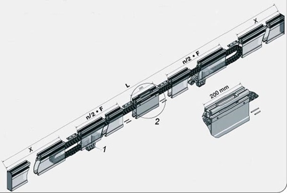
Micro flizz® assembled with 2 carriages in opposite directions - total length 10,000 mm, distributed over 2 channels of 3,000 mm each, the infeed module (200 mm) and 2 channel each with a residual length of 1,900 mm.
Bi = e-chains® internal width
R = bending radius [mm]
n = number of channel pieces
S = travel distance = L- 300[mm]
F = field length [mm]
L = total length [mm]
X = remaining length [mm]
MFG2.06.10.018.5000/2000 Version MF06
MFG2.08.18.035.5000/2000 Version MF08
MFG2.10.50.075.5000/2000 Version MF08
MFG2 = micro flizz® 2 carriages running in opposite directions
06./08./10. = Version (Series)
10./18./50. = e-chain® inner widths
018./035./075. = Bending radius [mm]
5000/2000 = Total length/field length [mm]
This is how you work out the number of channel sections required (n):
n=2*(L-200)/(2*F)
Then round the result down.
1 = Fixed end
2 = Moving end (-carriage)
F = Recommended channel length
Bi = Series 06: 10 mm / Series 08: 18 mm / Series 10: 50mm
hi = Series 06: 11mm / Series 08: 13 mm / Series 10: 20 mm